410 Signal Test Timer

|
The Model 410 Signal Test Timer has several capabilities that address various operations and signal related needs.
- Portable. Operates on furnished, plug-in 120VAC to 12VDC power supply or local battery, or Battery Kit accessories. Can also be installed on a permanent basis.
- Data from tests is recorded and can be downloaded. Download is implemented with the use of HyperTerminal (r), a program provided with Windows(r) operating system, or other standard communication program, through a USB port. Complete instructions for downloading, the printing of reports, etc., are provided in the Instruction Manual for the Model 410 Signal Test Timer.
- Determines Train Speed (PN: 410-18 Train Speed Transducer Kit and PN: 330-23T Battery Kit or 330-24 Battery Kit req'd) - install Train Detector Transducers on same rail, 100 feet apart. Connect cables to the Train Detector Transducers and the Timer Speed Interface. Attach power source (Battery Kit, etc.) to the Timer. Connect Timer Speed Interface to the Timer and wait for trains to pass. The installation process takes approximately thirty minutes to complete, once access to the track has been granted by the dispatcher. See hook-up diagram below.
- Determines Activation Lag & Throw Times of Switch Machines - Dry set of contacts from switch machine normal and reverse indications are connected to the Form C Inputs and normal and reverse voltages from the switch machine control point are applied to the Automatic Inputs.
- Determines Code Relay Rates - connect front and back contact of code relay to Form C Inputs.
- Determines Transition Times of Searchlight Signals - Connect normal and reverse contacts of searchlight signal to Form C Inputs
- Determines Activation Times of Solenoids equipped with contacts.
|
| Typical field hook-up.
|

|
Specifications
Accuracy: +/- 0.001 Seconds
Input Voltage: 10-16VAC or VDC (must match relay under test)
Operating Current: Minimum 60mA AC or DC, and will depend on relay load
Coil Output Voltage: Varies with and is less than input voltage depending on coil value.
Sense Input Isolation: Opto Coupler
Environmental Operating Temperature Range:
LCD Display: +15 deg. to +160 deg. F
Timer Functions: -40 deg. F to +160 deg. F
Timer Messages Displayed on LCD Screen:
Code Relay:
Code Rate
Period in Milliseconds
On Time Percentage
Off Time Percentage
Normal or Time Delay Relays:
Time Pick
Time Drop
Automatic Mode:
Activation Lag Times
Normal Throw Time
Reverse Throw Time
Speed Mode:
Speed in Miles Per Hour or Kilometers Per Hour (user selected)
Speed in Feet Per Second or Meters Per Second (user selected)
| ORDERING REFERENCES |
| Description |
Part Number |
| Model 410 Signal Test Timer, w/padded case, 500mA DC Power Supply & six 8 ft leads |
410-1 |
| Train Speed Transducer Kit (includes 2 transducers, Timer Speed Interface, Cable with Spools and Full-Kit Carry Cases |
410-18 |
| Battery Kit, 1.2AH w/Charger, to mount in padded case of Timer |
330-24 |
| Battery Pack, 3.0AH, w/Charger, Carrying Case & Connector |
330-23T |
| Carry Case (HD canvas for Timer and 3.0AH Battery Kit |
506BZB |
410-2 Train Speed Timer

|
The Model 410 Train Speed Timer allows the user to time trains, record the data, then download the recorded information on to a computer for analysis and other purposes. See below for a typical field hook-up.
- Portable. Operates on furnished, plug-in 120VAC to 12VDC power supply or local battery, or Battery Kit accessories. Can also be installed on a permanent basis.
- Determines Train Speed (PN: 410-18 Train Speed Transducer Kit and PN: 330-10T Battery Kit or 330-24 Battery Kit req'd) - install Train Detector Transducers on same rail, 100 feet apart. Connect cables to the Train Detector Transducers and the Timer Speed Interface. Attach power source (Battery Kit, etc.) to the Timer. Connect Timer Speed Interface to the Timer and wait for trains to pass. Data collected is downloadable. The instalation process takes approximately thirty minutes to complete, once access to the track has been granted by the dispatcher.
- Download operation is implemented with the use of HyperTerminal (r), a program provided with Microsoft Office (r), or other standard communication program. Complete instructions for downloading, the printing of reports, etc., are provided in the Instruction Manual for the Model 410 Train Timer.
|
| Typical field hook-up.
|

|
Specifications
Accuracy: +/- 0.001 Seconds
Input Voltage: 10-16VAC or VDC
Operating Current: Minimum 60mA AC or DC
Coil Output Voltage: Varies with and is less than input voltage depending on coil value.
Sense Input Isolation: Opto Coupler
Environmental Operating Temperature Range:
LCD Display: +15 deg. to +160 deg. F
Timer Functions: -40 deg. F to +160 deg. F
Timer Messages Displayed on LCD Screen:
Speed Mode:
Speed in Miles Per Hour or Kilometers Per Hour (user selected)
Speed in Feet Per Second or Meters Per Second (user selected)
| ORDERING REFERENCES |
| Description |
Part Number |
| Model 410 Portable Train Speed Timer, w/padded case, 500mA DC Power Supply & 410-18 Transducer Kit |
410-2 |
| Train Speed Transducer Kit (included 2 transducers, Timer Speed Interface, Cable with Spools and Full-Kit Carry Case) |
410-18 |
| Battery Kit, 1.2AH w/Charger, to mount in padded case of Timer |
330-24 |
| Battery Pack, 7.0AH, w/Charger, Carrying Case & Connector |
330-10T |
| Timer and 7.0AH Battery Kit Carry Case (HD canvas) |
506BZB |
|
FRA Rules That Apply
| Satisfy Requirements of FRA Signal Rules With Our Test Equipment |
| Rule # |
Rule Description |
S & C Equipment |
| 234.213 |
Rule for Grounds |
Model 360 Ground Finder |
| 234.249 |
Ground Tests |
Model 360 Ground Finder |
| 234.267 |
Cable Insulated Joint Inspection |
Model 336 Megohmmeter & Arrestor Tester |
| 236.2 |
Rule for Grounds |
Model 360 Ground Finder |
| 236.107 |
Ground Tests |
Model 360 Ground Finder |
| 234.108 |
Cable Insulation Resistance Tests |
Model 336 Megohmmeter & Arrestor Tester |
Shortcut to Specific Products
Notes on Calibration
Today's quality-driven railroad respects the need for annual calibration of test equipment, and budgets accordingly. S&C Distribution Company, appreciates the requirement, but does not agree that it is an expense that must be absorbed every year. In our effort to better serve our customers we have done something about calibration.
First of all, our modern meter equipment is designed and built to be more stable than those devices configured around earlier technology. Secondly, because we know the environment in which our products are used, we protect our test equipment from some of the "screwdriver lightning" that causes meters to lose calibration. Thirdly, in the case of our Megohmmeters and Ground Finder, we make available Calibration Check Devices that allow you to confirm calibration rather than require your Megohmmeter or Ground Finder be sent in for service on the chance that it is out of calibration. Due to the operating requirements of the Megohmmeters, a Calibration Check Device comes with every unit. With the Ground Finder, the Calibration Check Device is an accessory that is not required with every unit. In fact, we suggest that one per Supervisor or Manager is sufficient. A calibration check is really required only once per year.
Why should you absorb the cost of paying for the calibration service itself, the cost of shipping your Megohmmeter or Ground Finder back and forth and the cost of maintaining swing units to insure that testing schedules are met? You do not have to absorb these costs if you follow our Calibration Check Procedures for our 335/336 Megohmmeters and our 360 Ground Finder and make use of the appropriate Calibration Check Device. Contact us for further details.
 Substantially reduces testing time. No buttons to push or cranks to turn. Built-in alarms sound when insulation resistance values reach 500K ohms and 200K ohms. You do not even have to look at the tester until an alarm sounds. As an Arrestor Tester, unit displays actual firing voltage of lightning arrestor after non-destructive test, up to the operating voltage of the Megohmmeter. Our 335 Megohmmeter product group offers a testing voltage of 250VDC. This voltage matches the FRA requirements for testing on-board cab signal system equipment. The Kit descriptions parallel those of the Kits for the 336, 600V Megohmmeter. To order substitute �335� for the �336� in the below Kit listings.
| ORDERING REFERENCES |
| Description |
Part Number |
| Model 336 600V, Kit incl. Leads, 120 VAC Charging Adapter, In-Vehicle, Cal Check Device, Shoulder Harness, and Zipper padded case. |
336-1003 |
| Model 336 600V, Kit incl. Leads, 120 VAC Charging Adapter, In-Vehicle, Cal Check Device, and Zippered padded case. |
336-1006 |
| Model 336 600V, Kit incl. Leads, 120 VAC Charger Adapter, In-Vehicle, Cal Check Device 10K, and Zippered padded |
336-1007 |
|
 The 336 Megohmmeter/Arrestor Tester has been found to be effective in testing lightning arrestors used by the telecomm industry. In the Arrestor Tester mode, 600VDC is generated at a non destructive current to test fire lightning arrestors. Upon firing, the actual firing point of the arrestor is displayed on the voltmeter. A special configuration of our product has been developed to address this telecomm application. The primary differences between this product and the signal-oriented Megohmmeter are the leads and probe tips. Five foot, pluggable silicone leads are accompanied by two sets of probe tips that accommodate the full range of arrestor configurations in common telecomm use today: safety-jaw grips and safety-spring hook tips (both types depicted here) are furnished.
| ORDERING REFERENCE |
336-1002 |
|
 Our Model 360 Ground Finder is a stand-alone tool designed to simplify, expedite and standardize the testing for grounds required by FRA Rules No. 234.249 and 236.107. Testing voltage is 22.5 VDC in both Test and Confirm modes, reflecting a standard common with several railroads, avoiding "masking" below 20VDC, and out of normal signaling voltage ranges. Unique �touch and go� operation greatly accelerates testing. And, with the 360 tester it is not necessary to switch polarities to detect both positive and negative grounds where circuit voltage is 16VDC, or less. For circuit voltages in excess of 16VDC, it will be necessary to make both polarity tests. When switching polarities is necessary, a simple push-button feature is supplied to enable quick, temporary reversal of polarities. Also, to guard against detecting �ghost� grounds, meter sensitivity is limited to 1000 ohms per volt, matching the Simpson TS-111(r). Battery storage compartment is an easy-access, drawer-like device that is located on the right side of the tester. Unit comes complete with leads and a black, zippered carrying pouch with space for lead storage.
| ORDERING REFERENCES |
| Description |
Part Number |
| Model 360 Ground Finder w/Crocodile Clip Leads, Zippered Tool Pouch |
360-4 |
| Above, in Dual Meter Case |
360-1003 |
| Above, in Dual Meter Case w/Calibration Check Device |
360-1002 |
| Dual-Meter Kit paring the 360-4 Ground Finder with our355 Signalman's Meter |
355-1360 |
| Calibration Check Device f/360 |
360-30 |
| Dual Meter Case for use with alternative meter |
360-20 |
| Carrying Pouch, Replacement |
360-12 |
| 9 VDC Lithium Battery, Replacement |
04-1015 |
| Lead Set, Crocodile Clip Leads, Replacement |
360-19 |
|
 If you use the Ground Finder to do your monthly and quarterly ground tests you will need a voltmeter to do your voltage tests. The Dual Meter Case provides space for the Ground Finder and a Fluke-like VOM. Use of this zippered, padded case allows you the convenience of having only one item to carry into the bungalow when doing the tests. There are even two separate, zippered pockets to keep the leads properly sorted.
| ORDERING REFERENCE |
360-20 |
|
 A 1% accuracy test load accessory that matches the ground detection calibration point of the 360 Ground Finder. This Calibration Check Device permits you to confirm calibration of the Tester, its alarm circuitry and its operation. The Device also permits you to extend the once a year calibration cycle until the readings change. We strongly recommend that this device be purchased and used.
| ORDERING REFERENCE |
360-30 |
|

|
This tool is intended to be an easier-to-use replacement for business cards, credit cards and various other field-expedient means employed by signalmen to block contacts when making maintenance checks, required tests and repairs. Large size of Tool helps to remind user to remove it at the completion of his tests or other maintenance procedures. Narrow and wide ends of Tool are both usable for contact blocking. Nylon crossbar prevents Tool from falling down into the interior of switch machine and circuit controller housings. Examples of applications:
- Block crossing gate mechanism motor up contacts to permit single mechanism mainenance where mechanisms do not have a power cutout test link.
- Block switch machine power contacts to permit hand cranking for obstruction and restoring feature tests.
- Selectively block switch circuit controller contadcts in multiple to prevent closing during hand operated switch obstruction tests, contact closure tests, etc.
- Block switch machine contacts to expedite and simplify cable meggering and crosschecking; include internal switch machine and motor wiring in the same test.
|
|
236-103 Signal and Lamp Load Simulator

- For Use In New Construction and Maintenance
- Simulates Three Signals With Lamp Load (10 Ohms) and Color Indication
- Switches Are Provided To Test "Lamp Out" Response
- Separate Common For Red Signal
- Housing Face Surface Is Writeable (Dry Erase) For Signal Tag Names
- Not Polarity Sensitive
- Lamp Input Voltage 8 - 16 Volts AC or DC
- Comes With Polarized-Plug Cord Set (2, 4 or 8 ft lg) and Carry Bag for Cords
| ORDERING REFERENCES |
| Ref |
Description |
Part Number |
| 1 |
236-103 Kit w/3 two ft, pluggable cord sets |
236-103-02 |
| 2 |
236-103 Kit w/3 four ft, pluggable cord sets |
236-103-04 |
| 3 |
236-103 Kit w/3 eight ft, pluggable cord sets |
236-103-08 |
|
236-233 and 236-353 Signal Color Test Units

Train traffic has condensed the time available to maintainers to conduct tests. Sometimes the dispatcher calls for the track back before the tests are completed. The S&C Signal Color Test Units can substantially reduce the time it takes to conduct any test that requires confirming which signal has been lit. With our Test Units, verify the field aspects, then do your work. No need to have a second person �calling colors�. No need to go outside and look. Saves the same amount of time and manpower when cutting over new-construction signal systems.
These test units are designed and built to provide reliable, accurate reporting of signal aspects from within the bungalow. Our Signal Color Test Units are electrically sound: are reverse polarity protected; Red has a discrete ground, other colors share a ground; very high internal impedances preclude crossover voltages; plugs are wired in parallel; and LED �signals� on Test Units bridge energy from the signal lamp river source, insuring that LED�s reflect the aspect being displayed in the field signal head and avoid becoming an additional or shunting load on the circuit.
Choice of two signal configurations (2 and 3), two light output voltage ranges (10-12VDC and 10-50VDC) and three connecting wire lengths (2, 4 and 8 feet long)
| ASSEMBLIES |
| Ref |
Description |
W/2 ft Wires |
W/4 ft Wires |
W/8 ft Wires |
| 1A |
2 Signal Color Test Unit, 10-12V |
236-353-2 |
236-353-4 |
236-353-8 |
| 1B |
Above, w/Bag |
236-353-2Z |
236-353-4Z |
236-353-8Z |
| 1C |
2 Signal Color Test Unit, 10-50 V |
236-350-2 |
236-350-4 |
236-350-8 |
| 1D |
Above w/Bag |
236-350-2Z |
236-350-4Z |
236-350-8Z |
| 2A |
3 Signal Color Test Unit, 10-12V |
236-233-2 |
236-233-4 |
236-233-8 |
| 2B |
Above, w/Bag |
236-233-2Z |
236-233-4Z |
236-233-8Z |
| 2C |
3 Signal Color Test Unit, 10-50V |
236-250-2 |
236-250-4 |
236-250-8 |
| 2D |
Above, w/Bag |
236-250-2Z |
236-250-4Z |
236-250-8Z |
| Replacement Parts |
| Ref |
Description |
W/2 ft Wires |
W/4 ft Wires |
W/8 ft Wires |
| 3 |
6 Wires and Plug |
236-353-1-6-2 |
236-353-1-6-4 |
236-353-1-6-8 |
| 4 |
Bag, Carry, Zippered |
506ZB |
506ONBZB |
506ONBZB-24 |
| Ref |
Description |
Part Number |
| 5 |
2 Color Signal Test Unit, 10-12V, less plug & wire sets |
236-353 |
| 6 |
2 Color Signal Test Unit, 10-50V, less plug & wire sets |
236-350 |
| 7 |
3 Color Signal Test Unit, 10-12V, less plug & wire sets |
236-233 |
| 8 |
3 Color Signal Test Unit, 10-50V, less plug & wire sets |
236-250 |
| 9 |
Hangar, adjustable, 4 in. |
236-353-1 |
|
Model 400 Train Stop Inductor Tester
 Tester is designed to identify the impedance range of the inductor choke coil with a Laminated Test Bar accessory simulating the on-train receiver. A reading above or below the acceptable range indicates a bad inductor. This test simulates a live, operational environment which is the most complete form of test.
To help insure that the Tester internal battery is not depleted unnecessarily, the power switch is a dependent push-button. The power switch must be depressed to conduct a test. At all other times the Tester is turned off. The Model 400 Train Stop Inductor Tester comes in a rugged, fiberglass-reinforced, poly-vinyl case complete with leads, charger for the build-in, lead-acid gel cell, and removable, padded shoulder harness.
| ORDERING REFERENCES |
| Description |
Part Number |
| Model 400 Train Stop Inductor Tester |
400-1 |
| Laminated Test Bar |
400-2 |
|
401 Impedance Bond Integrity Tester
 Easily portable Tester used to test conventional impedance bonds (not Wee-Z type impedance bonds). Allows user to determine the impedance of a bond at selectable test frequencies of 60 Hz and 156 Hz. Indicator flashes at 1-2 ohms. Meter reading covers a non-inductive resistance range of zero to 100 ohms. Operates on one 9V battery (included). Push-button controlled LED's light meter for 15 seconds at a time for nighttime use. Comes complete with zippered, padded case and leads equipped with BU-11 battery clips for gripping impedance bond terminal lugs.
| ORDERING REFERENCES |
| Description |
Part Number |
| Model 401 Impedance Bond Integrity Tester |
401-1 |
|
FRA Rules That Apply
| Satisfy Requirements of FRA Signal Rules With Our Test Equipment |
| Rule # |
Rule Description |
S & C Equipment |
| 234.229 |
Shunting Sensitivity Tests |
Model 340 Time Activated Testing Shunt |
|
|
506 Series Testing Shunts |
| 234.259 |
Warning Time Tests |
Model 340 Time Activated Testing Shunt |
| 236.51 |
Rule for Track Circuits |
Model 340 Time Activated Testing Shunt |
|
|
506 Series Testing Shunts |
| 236.56 |
Rule for Shunting Sensitivity |
Model 340 Time Activated Testing Shunt |
|
|
506 Series Testing Shunts |
| 236.104 |
Shunt Fouling Circuit Test |
506 Series Testing Shunts |
Shortcut to Specific Products
Notes on Shunt Quality
While seemingly basic, uncomplicated products, testing shunts are critical to the proper operation of the signal system. In keeping with this criticality, every Shunt manufactured by S&C Distribution Company, including zero ohm shunts, is assigned a Serial Number and is tested for proper value or values prior to shipment. The test results are recorded by Serial Number, in a permanent record, for traceability.
Further, every aspect of our Shunt design has an engineering justification. Being aware of significant shortfalls in resistance accuracy and durability of other shunt products, we have reviewed our designs to eliminate, or design countermeasures for, every point where it would be possible for resistance to accumulate. These efforts have resulted in Shunts that, hand tight, will shunt your track circuits "the first time, every time", according to our many satisfied customers. On the subject of durability, one railroad considers our Shunts "ten year service life shunts".
How to Specify Shunt Resistance
With each of the below listed types of testing shunts where resistance values are involved note that there is one ordering reference for each type of connector (head-of-rail clamp, base-of-rail clamp), regardless of shunt resistance. Also note that within that ordering reference are blank spaces represented by dashed underscore lines ( _ _ ). This group of blank spaces is where you indicate the resistance value desired. Where two resistances are available in one shunt, two sets of dashed underscore lines are presented.
We have configured the ordering reference in this way because we offer an extensive line of standard resistances, can produce a shunt with virtually any resistance value you might request. As well as a shunt with multiple resistances values. Rather than create pages of ordering references, the only variation to which would be the resistance value itself, we let you fill in the blanks as appropriate. At present our standard resistance values are:
- 0.06 ohms
- 0.10 ohms
- 0.15 ohms
- 0.20 ohms
- 0.25 ohms
- 2.00 ohms
When completing the ordering reference to place your order, fill in the blanks with numbers in the exact sequences shown above. Do not include the decimal point. For example a 0.06 ohm shunt value would read: 0 6. If you need a resistance other than one of the values listed above, simply specify the value in the same sequence as shown. For example a 0.25 ohm shunt value would read: 2 5. If the value you require is two ohms (2:0) show it as "2X". Note that if you order a value other than one of those listed above, the lead time is 45 days to 60 days ARO. Please contact us for ordering instructions. Otherwise our Shunts are generally shipped from stock.
For transporting and storing Shunts. Heavy canvas with zipper. Standard size for all conventional Shunts; larger size for Imbedded Rail, 14 inch and 24 inch Fast Shunts.
| ORDERING REFERENCES |
| Description |
Part Number |
| Standard Size Bag |
506ZB |
| Larger Bag |
506BZB |
| Safety Orange Bag f/14" Handles |
506ONBZB |
| Safety Orange Bag f/24" Handles |
506ONBZB-24 |
|

|
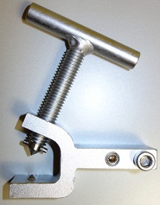
S&C Railroad Grade Shunt Clamps bring strength and conductivity that have not been achieved in shunt clamps before, but should have been. They also introduce a new concept; maintainability, that does not compromise shunt reliability. And, to address today�s conditions, our head-of-rail clamps have the widest reach and longest legs to permit accommodation of the worst lipped-over rail, yet will clamp to rail sections from 70 lb. to 140 lb. This design also results in a clamp that does not spread as it is tightened on the rail, maintaining a zero ohm connection.
Our Base-of-Rail Clamp (see photo at left) has been reconfigured to be �Easy-On�. The Connector for the shunt wire also serves as a handle, permitting the user to shove the Clamp onto the rail with a very minimal effort. Usually no digging away of ballast is required. Additional features of the �Easy-On� base-of-rail clamp are: that it is shaped to match the rail base to prevent �walking�, clearance requirements between rail and ballast have been reduced to the absolute minimum, and the connector tip is an integral part of the clamp, eliminating a point of potential parasitic resistance.
Both Clamps and their T-Screws and Connectors feature 55-60 Rockwell C heat-treat hardening and hard tool chrome plating for durability and resistance to rust and corrosion. These Clamps are available for purchase separately.
|
|
| ORDERING REFERENCES |
| Ref |
Description |
Part Number |
| 1 |
Easy-On Base-of-Rail Clamp, complete |
340-100-18 |
| 2 |
Lock-Down Easy-On Base of Rail Clamp, complete |
340-100-18NW |
| 3 |
Head-of-Rail Clamp, complete |
340-200 |
| 4 |
Lock-Down Head-of-Rail Clamp, complete |
340-200NW |
|
|

|
Our �NW� Series, zero ohm, hardwire shunts are intended for use by maintenance of way personnel to clear highway crossing signals during track maintenance operations and by operating department personnel when conducting efficiency or signal response tests of train crews. No. 6 AWG welding cable is used to provide maximum conductivity, flexibility and ease of use. Shunt wires are available in safety orange, red and black. These Shunts come with S&C railroad-grade clamps with special, lock-down nuts and washers to help insure stable, long-term connection to the rail.
|
| ORDERING REFERENCES |
| Description |
Black Wire |
Red Wire |
Orange Wire |
| 0 Ohm w/Base-of-Rail Clamps |
506-00BNW |
506-00RNW |
506-00ONW |
| 0 Ohm w/Head-of-Rail Clamps |
506-00BNWH |
506-00RNWH |
506-00ONWH |
|
 Zero ohm, hardwire testing shunts are a basic signal testing tool. Highly flexible No. 6 AWG welding cable is used to provide maximum conductivity, flexibility and ease of use. Shunt wires are available in bright orange, red and black. These Shunts come with S&C railroad-grade base or head-of-rail clamps or file handles.
| ORDERING REFERENCES |
| Description |
Black Wire |
Red Wire |
Orange Wire |
| 0 ohm w/Base Clamps |
506-00BB |
506-00RB |
506-00OB |
| 0 ohm w/Head Clamps |
506-00BH |
506-00RH |
506-00OH |
| 0 ohm w/File Handles |
506-00BF |
506-00RF |
506-00OF |
|
 Rugged, traditional, clamp-type testing shunts for adjusting and testing track circuits. Unique design assures extremely low probability of change of resistance values within the shunt assembly. Switchable between common testing values and zero ohms with test nut. Very close electrical tolerances make these tools highly accurate. Head-Of-Rail Clamps accommodate lipped-over rail and an unusually wide range of rail sections; 70 to 140 lb. Can be purchased with one or two resistances and zero ohms in one shunt.
| ORDERING REFERENCES |
| Description |
1 Resistance |
2 Resistances |
| Base-of-Rail Clamps |
506-( _ _ )B |
506-( _ _ ) ( _ _ )B |
| Head-of-Rail Clamps |
506-( _ _ )H |
506-( _ _ ) ( _ _ )H |
|
 A shunt configuration developed in response to customer request, these clamp-type testing shunts depart from the traditional by placing the Resistor Bracket on a standoff from one of the head-of-rail clamps. This design moves the Resistor Bracket out of the middle of the shunt wire, significantly reducing the potential of the Bracket to snag, being damaged, etc. It also makes it easier to vary the resistance values, by placing the adjustment point at top-of-rail height, rather than on the ground. In addition to being unique, these shunts are built to the usual S&C specification, heavy-duty, railroad grade, highly accurate and reliable.
Ordering References
(Insert resistance value or values .06, .10, .15, .20, .25, 2.0, where blanks in parenthesis are shown, omitting decimal. Use �2X� for 2.0 ohm value).
To have a heavy-duty, protective, canvas Shunt Bag furnished with your Shunt, add a �Z� behind the �H� in the ordering reference.
| ORDERING REFERENCES |
| Description |
Part Number |
| Single resistance & Zero |
506CB-(_ _)H |
| 2 resistances & Zero |
506CB-(_ _)(_ _)H |
| 3 resistances & Zero
|
506CB-(_ _)(_ _)(_ _)H |
| CB Clamp with Mounting Bracket for Resistor |
340-200CB |
|
 Rugged, clamp-type testing shunts, with special "Open" option, for adjusting and testing track circuits. Shunt can be opened without removing clamps from the rail. Unique design of the overall shunt assures extremely low probability of resistance variations within the shunt assembly. Switchable between common testing values, zero ohms and open with test nuts. Very close electrical tolerances make these tools highly accurate. Both base-of-rail and head-of-rail clamp versions are available. Our Railroad Grade Head-Of-Rail Clamps accommodate lipped-over rail and an unusually wide range of rail sections; 70 to 150 lb.
| ORDERING REFERENCES |
| Description |
1 Resistance |
2 Resistances |
| Base-of-Rail Clamps |
506-( _ _ )OB |
506-( _ _ ) ( _ _ )OB |
| Head-of-Rail Clamps |
506-( _ _ )OH |
506-( _ _ ) ( _ _ )OH |
|
 Track Jumpers are used to facilitate track maintenance operations. They are particularly helpful in keeping crossing warning systems from being unnecessarily activated. Extended length allows the bypass of insulated joint replacement activities. No. 6 AWG welding cable is used to provide maximum conductivity, flexibility and ease of use. Wire insulation colors available include black, red and orange. Comes with S&C railroad grade base-of-rail or head-of-rail clamps. Track Jumpers with Base-of-Rail Clamps are furnished with "NW", lock-down type of clamps. Twenty foot length listed here. Lengths available range from six feet to 350 feet.
| ORDERING REFERENCES |
| Description |
NW Base Clamps |
Head Clamps |
| Track Jumper, 20ft, black wire |
506-120BB |
506-120-BH |
| Track Jumper, 20ft, red wire |
506-120 RB |
506-120RH |
| Track Jumper, 20ft, orange wire |
506-120OB |
506-120OH |
|
 Rugged, file-type testing shunts for making quick shunting tests or for adjusting and testing track circuits in flush rail environments. Can be switched between common testing values and zero ohms. Very close electrical tolerances make these tools highly accurate. Can be purchased with two resistances in one shunt.
| ORDERING REFERENCES |
| Description |
Part Numbers |
| File Shunt w/one resistance |
506-(_ _) |
| File Shunt w/two resistances |
506-(_ _) (_ _) |
|
 A new way to connect testing shunts to the rail temporarily and easily. 506P Shunts (AC-Only and single resistance shunts shown to the left) utilize the probe concept, providing railroad-durable 12.5 inch Probes (including handle length with tips that are file hard. The 12 inch length makes reaching rail to rail with enough leverage to effect a reliable shunt doable, and the hardened tips insure long service life. Probes are hard tool chromed after fabrication and heat treating for resistance to rust, corrosion, etc.
Our Probe Shunts are especially helpful in making "rolling" shunt and shunt fouling tests. Unique design assures extremely low probability of resistance variation within the Shunt. Very close electrical tolerances make these tools highly accurate. Every Shunt furnished by S&C Distribution Company is factory tested for proper resistance value(s). Each Shunt is serial numbered and the values of resistance are recorded with the serial number for traceability.
Probe Shunts come in several configurations: Zero ohm (hardwire), switchable with test nut between Zero ohm and one or two common testing resistances and in an AC-Only configuration for specialized crossing warning system testing applications.
| ORDERING REFERENCES |
| Description |
Part Number |
| Hardwire Shunt |
506P-00 |
| Single resistance & Zero |
506P-(_ _) |
| 2 resistance & Zero |
506P-(_ _) (_ _) |
| AC-Only Shunt |
516P-AC |
| Handle, w/Probe |
506P-1 |
| Probes, only, 1 Pair |
506P-2 |
|
 AC-Only Shunts can permit the set-up and testing of audio frequency and motion responsive track circuits without disrupting the operation of DC train detection track circuits. When used safely and carefully (see instructions furnished with the Shunts) this capability can significantly improve a signalman's productivity and improve overall maintenance of crossing warning systems. A large, bright red warning label, incorporating key safety information contained in the instructions, is firmly mounted to the shunt cartridge. Shunts come with bright orange wire and either File Handles, Dual-Blade Handles, Warren Fast Shunt Handles (see following section for description of Warren Fast Shunt) and Head or Base-of-Rail Clamps. Note that, due to the safety implications should this Shunt be accidentally left on the track, we recommend against using this Shunt with Base-of-Rail Clamps.
| ORDERING REFERENCES |
| Description |
Part Number |
| Shunt w/File Handles |
516-F |
| Shunt w/Dual-Blade Handles |
516-DB |
| Shunt w/Warren Fast Shunt Handles (14 in.) |
516-WFS |
| Shunt w/Warren Fast Shunt Handles (38 in.) |
516-WFS38 |
| Shunt w/Head-of-Rail Clamps |
516-H |
| Shunt w/Base-of-Rail |
516-B |
|
 A very old idea resurrected by S&C Distribution Company, in response to considerable interest from signalmen. This concept greatly facilitates making quick on and off shunts required for shunt fouling tests, series shunting during cutovers, and for making shunt tests to confirm circuit performance during required monthly, quarterly and annual tests. Come in two handle configurations: with operating handles approximately 14 inches (3.0 lbs) and 38 inches (6.0 lbs) long. Any shunt wire manufactured by S&C Distribution Company can be equipped with these handles.
| ORDERING REFERENCES |
|
14 in. Handles |
38 in. Handles |
| Description |
Part Number |
Part Number |
| 0 ohm, hardwire |
506WFS-00 |
506WFS38-00 |
| 0 ohm and single resistor |
506WFS-(_ _) |
506WFS38-(_ _)
|
| 0 ohm and two resistors |
506WFS-(_ _) (_ _) |
506WFS38-(_ _)(_ _) |
| AC-Only Shunt |
516-WFS |
516-WFS38 |
|
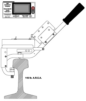 The Model 506 Circuit Testing Shunt with Meter includes an S&C Warren Fast Shunt (your choice of 14, 24 or 38 inch handles) with your choice of resistances, and built-in meter leads, with an S&C, AC/DC digital, low-temperature (-40 degF) Voltmeter (PN: 506-802, see separate listing in the �Insulated Joint Testing and Track Circuit Testing� section of this website). Switching the Shunt between �Open� and the resistance value or values ordered, accurate track circuit tests are achieved in seconds.
The Fast Shunt allows you to move quickly between shunting points, while connecting effectively to even the rustiest rail. A thumb screw firmly retains the 506-802 Digital AC/DC Voltmeter in its Instrument Mounting Bracket. While the most common configuration includes the 0.06 ohm resistance, more than one resistor can be included in the Resistor Bracket (resistance options include: 0.06, 0.10, 0.15, 0.20, 0.25 and 2.0 ohms), depending on handle length selected. As indicated in the ordering reference table below, Retro-Fit Kits are available for converting your conventional Warren Fast Shunt to a Circuit Testing Shunt. Kits fit all Handles.
| ORDERING REFERENCES |
| Ref |
Handle Length |
Description |
Part Number |
| 12-5 |
14 in. |
Shunt with single resistance, Meter, Leads, Bag |
506WFSS-(_ _)VZ |
| 12-2 |
14 in. |
Shunt with single resistance, Leads & Bag |
506WFSS-(_ _)LZ |
| 12-1 |
24 in. |
Shunt with single resistance, Meter, Leads, Bag |
506WFSS24-(_ _)VZ |
| 12-1A |
24 in. |
Shunt with single resistance, Leads & Bag |
506WFSS24-(_ _)LZ |
| 12-6 |
All |
Retro-Fit Kit, Meter, Leads, single resistance |
506WFSSV-RFK(_ _) |
| 12-4 |
All |
Retro-Fit Kit, Leads, single resistance |
506WFSSL-RFK(_ _) |
| 12-9 |
38 in. |
Shunt with single resistance, Meter, Leads |
506WFSS38-(_ _)V |
| 12-8 |
38 in. |
Shunt with single resistance, Leads |
506WFSS38-(_ _)L |
|

Adjustment and testing of track circuits that operate in an imbedded, or flush, rail environment are difficult if not impossible with conventional clamp type shunts. Even File or Probe Shunts, while effective for quick tests of such track circuits can be difficult to use for adjustment purposes. S&C Distribution Company offers track shunts equipped with easy-to-use, specialized clamps for use in imbedded track.
Whether the flangeway is created with plastic, rubber, metal, concrete or macadam, the 508 Series Power Imbedded Rail Testing Shunts provide a very effective means of applying firm electrical connections to the rail. Accurate and reliable adjustments to, and testing of, track circuits working in such environments are readily achieved.
Unique design of the connectors and shunt wires assures extremely low probability of resistance variations within the shunt. Switchable between common testing values and zero ohms with test nut. For the large variety of resistance values available, see the Section titled �How To Specify Shunt Resistance�, at the beginning of the Testing Shunts page of this web site. Very close electrical tolerances make these tools highly accurate. Clamps are furnished with handles for portability. Carry Bags are also available.
| ORDERING REFERENCES |
| Reference |
Description |
Part Number |
| 1 |
Zero Ohm, Hardwire Power Shunt |
508-00 |
| 2 |
Single Resistance & Zero Power Shunt |
508-(_ _) |
| 3 |
Dual Resistance & Zero Power Shunt |
508-(_ _) (_ _) |
| 4 |
Larger Shunt Carry Bag, HD, zippered |
506BZB |
| Replacement Parts |
| 5 |
Zero Ohm, Hardwire Power Shunt Wire S-Assy |
508-00B-1 |
| 6 |
Single Resistance & HW Shunt Wire S-Assy |
508-(_ _)-1 |
| 7 |
Dual Resistance & HW Shunt Wire S-Assy |
508-(_ _) (_ _)-1 |
| 8 |
Power Imbed. Rail Shunt Clamp S-Assy |
508-25-2 |
| 9 |
Connector, Short Tip, f/Imbed. Clamp, compl |
508-25-2-3A |
| 10 |
Rounded Tip T-Screw f/Imbed. Clamp |
508-25-1-1 |
|
 Obstruction Gauges are used to comply with FRA required tests of track switches. They are used to determine if a power operated switch or a hand operated switch and lock movement has been adjusted properly. Proper adjustment is deemed to occur when the switch cannot be locked up when the appropriately sized obstruction is placed between the switch point and stock rail, six inches from the end of the switch point.
The design concept S&C Distribution Company has employed provides four gap gauges of standard values and in combinations that enable fast changes over to values used for different tests. The design also assures more stable, self-retaining mounting to the rail during tests.
Gauge No. 236-382B (Dwg. To the left) offers the gap gauges most common to signal testing (AREMA standard). Gauge No. 236-382A provides a 5/16th inch gap gauge that addresses special adjustment to M-23 Switch Machines where the practice of floating off the lock rods occurs. At locations where a split point derail is operated with a switch machine or a hand operated switch and lock movement, we offer a special gauge, No. 236-382C, where a � inch gap gauge is provided.
| ORDERING REFERENCES |
| Description |
Part Number |
| Switch Obstruction Gauge with 3/16, �, 5/16, and 3/8 Gap Gauges Side 1 with 3/16 & 5/16 in Gaps and Side 2 with � and 3/8 in Gaps |
236-382A |
| Switch Obstruction Gauge with 1/8, 3/16, � and 3/8 in Gap Gauges
Side 1 with 1/8 and � in. Gaps and Side 2 with 3/16 and 3/8 in. Gaps |
236-382B |
| Switch Obstruction Gauge with 3/16, �, 3/8 and 1/2in. Gap Gauges
Side 1 with 3/16 and 3/8in. Gaps and Side 2 with � and 1/2in. Gaps |
236-382C |
| Switch Obstruction Gauge with 1/8, 3/8, � and � in. Gap Gauges
Side 1 with 1/8 and 3/8in. Gaps and Side 2 with � and 1/2in. Gaps |
236-382D |
|
 Our New Guard Rail Clamp Shunt, with a Guard Rail Clamp on one end as pictured above, is a shunt that we make for applications where track circuits fall in areas, where guard rails are also used. The Clamp is designed to allow the end to which the shunt wire attaches to, fit into the flangeway. The wire connector passes over the guard rail, allowing the shunt wire to cross the track unobstructed, to another Guard Rail Clamp or conventional clamp if another guard rail is not in service. The Guard Rail Shunt is available in two configurations. One with Guard Rail Clamps on both ends, and one with a Guard Rail Clamp on one end, and a conventional clamp on the other.
| ORDERING REFERENCES |
| Description |
1 Resistance |
2 Resistances |
| Guard Rail Shunt w/ One Guard Rail Clamp And One Conventional Base-of-Rail Clamp |
506GR-( _ _ )B |
506GR-( _ _ ) ( _ _ )B |
| Guard Rail Shunt w/One Guard Rail Clamp And One Conventional Head-of-Rail Clamps |
506GR-( _ _ )H |
506GR-( _ _ ) ( _ _ )H |
| Guard Rail Shunt w/ 2 Guard Rail Clamps |
506GR2-( _ _ ) |
506GR2-( _ _ ) ( _ _ ) |
|
Pictured above is the Clamp Bracket version of the 506 Series, 5-Resistor Commissioning and Testing Shunt that provides the five individually selectable resistance values (0.06 Ohm, 0.12 Ohm, 0.30 Ohm, 0.40 Ohm and 0.50 Ohm) intended for use in set-up calibration and sensitivity testing of GCP-4000 � island circuits.
Set-up is achieved by clamping the shunt with the appropriate (generally established by the railroad engineering office) resistance value, at the receiver feed wires, then activating calibration of the island card.
Once calibration is completed, a 0.06 ohm shunt (also included in the 506 Five Resistor Shunt) is used at the attach points of both transmit and receive sets of wires of the GCP-4000 � to satisfy the FRA requirement that the circuit will drop out on application of a 0.06 ohm shunt.
In a maintenance application, shunting sensitivity can be determined by clamping the 506 Five Resistor Shunt at the receiver feed wires and changing the resistor settings until the island circuit drops. That value is the shunting sensitivity.
| ORDERING REFERENCES |
| Item No |
Description |
Part Number |
| A |
Shunt, Clamp Bracket, 5 Resistance; .06,.12,.30,.40,.50, Bag |
506CB-612345Z |
| B |
Above, but Base of Rail Clamps, Bag |
506-612345Z |
|
Model 340-120 Risley Temporary Track Wire Connector
 PROBLEM: Weather, time and equipment availability can interfere with proper connection or reconnection of track wires, bonds, hardwire shunts, etc. Other times, maintenance operations such as replacement of insulated joint plugs and repair of broken rail require quick, semi-permanent electrical connections. Through all of these variables, railroad operations must be kept as free-flowing as possible.
SOLUTION: S&C Distribution Company offers the 340-120 Risley Temporary Track Wire Connector, various lengths of pre-tinned interconnect wire, and Connector Blocks in two configurations that will address any of the above conditions. These products together allow quick, reliable, semi-permanent to permanent track wire connections.
|
Carry Bags for Temporary Track Wire Connectors
Note that Carry Bags are offered below as a means to corral the various parts, pieces and tools of a Temporary Track Wire Connector Kit. These are very rugged, military-style canvas bags, with heavy-duty zippers, strap handles and hard bottoms to make the load more manageable. Exterior snap-closure side pockets provide a place to separate and store tools. Two sizes of Bags are offered; Standard, 5 in. x 7 in. x 12 in., and Larger, 6 in. x 9 in. x 19 in. Configurations are also offered that include the appropriate tools for the two types of Connectors.
| ORDERING REFERENCES |
| Description |
Part Number |
| Risley Temporary Track Wire Connector, w/T-Screw |
340-120 |
| Risley Temporary Track Wire Connector w/Sq. Hd. Set Screw |
340-121 |
Risley Temp Track Wire Connector Kit (T-Screw)
(incl. 2 ea Connectors, one Th Wrench, one Hex Key, one Carry Bag) |
340-120K |
Risley Temp Track Wire Connector Kit (Sq. Hd. Set Screw)
incl. 2 ea. Connectors, one Th Wrench, one T-Wrench, one Hex key, one Carry Bag) |
340-121K |
| 5 Wire Connector Block w/Pigtail |
340-125 |
| 7 Wire Connector Block w/Pigtail |
340-127 |
| Interconnect Wire, Pigtail, 12 in. |
340-126-12 |
| Interconnect Wire, 4-Hole Bar Bond, 36 in. |
340-126-36 |
| Interconnect Wire, 6-Hole Bar Bond, 50 in. |
340-126-50 |
| Interconnect Wire, Temp. Hard Wire Shunt, 6 ft. |
340-126-6F |
| Interconnect Wire, Track Jumper, 20 ft. |
340-126-20F |
| 3/4 in. Thin Head Wrench |
340-120-18 |
| 1/4 in. Long Arm Hex Key |
340-120-19 |
| T-Wrench for Sq. Hd. Screw for 340-121 |
340-120-20 |
|
| Standard Carry Bag (5in.x7in.x12in.) for Connector Materials |
506ZB |
| Larger Carry Bag (6in.x9in.x19in.) for Connector Materials |
506BZB |
| Standard Carry Bag w/tools for 340-120 connector |
340ZB |
| Larger Carry Bag w/tools for 340-120 Connector |
340BZB |
| Standard Carry Bag w/tolls for 340-121 Connector (sq. hd) |
340ZBQ |
| Larger Carry Bag w/tools for 340-121 Connector (sq. hd) |
340BZBQ |
|
340-301 Series Temporary Power Bond Rail Clamp Connector
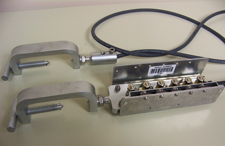
 The Model 340-301 Series Temporary Power Bond Rail Clamp Connector (TPBRC-Connector) is a rugged, field-tested and field-proven product. When properly installed it provides a zero ohm connection to the rail with the capacity to carry traction current, reliably. It will stay in place until it is removed, even in areas where track conditions are likely to vibrate less effective connection devices off the rail.
Application is simplified to insure the highest possibility that anyone using the product can use it correctly. It will mount to rail from 70 lb. to 140 lb. in size.
TOOLS - All necessary mounting adjustments can be made with the Special Wrench offered, that includes a square end that allows tightening of the square head set screws and a deep-well socket that allows tightening of all binding and jam nuts.
CARRY BAGS - Note that a Carry Bag is offered as a means to corral the various parts, pieces and tools of a Temporary Power Bond Rail Clamp Connector kit. This is a very rugged, military-style canvas bag, with heavy-duty zipper, strap handles and hard bottom to make the load more manageable. Exterior snap-closure side pockets provide a place to separate and store tools. Bag is offered appropriately sized at 6 in. x 9 in.
| ORDERING REFERENCES |
| Description |
Part Number |
| Temporary Power Bond Clamp Connector w/crimp connector for 250MCM stranded conductor |
340-301A |
| Above, but for 300 MCM stranded conductor |
340-301B |
| Above, but for 350 MCM stranded conductor |
340-301C |
| Above, but for 400 MCM stranded conductor |
340-301D |
| Above, but for 500 MCM stranded conductor |
340-301E |
| Kit including two Temporary Power Bond Connectors and Special Wrench in a Heavy-Duty Carry Bag (see below) |
Add "K" to any of the above ordering references |
| Special Wrench with 1/2" square socket and 3/4" deep-well socket, L-shaped |
340-301-18 |
| Heavy Duty Carry Bag (6 in. x 9 in. x 19 in.) |
506BZB |
|
340-301-18 Connector Wrench
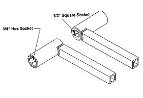 Rugged, hard tool-chromed, wrench developed to make various S&C Distribution Company temporary connectors easier to install and remove. Among others, use with 340-120 Temporary Track Wire Connector with squarehead bolt lock and 340-301 Temporary Power Bond Connector. 3/4 in. hex, deepwell socket reaches over squarehead bolts that protrude up to 2 inches above the nut to be engaged by the socket. Reverse end of the socket will engage 1/2 in. squarehead bolt to tighten it. Handle is 6 in. long, gives maximum torque necessary to cinch bolts and nuts in place. Drawing to the left shows both ends of the socket.
| ORDERING REFERENCE |
340-301-18 |
|
FRA Rules That Apply
| Satisfy Requirements of FRA Signal Rules With Our Test Equipment |
| Rule # |
Rule Description |
S & C Equipment |
| 234.235 |
Rule for Insulated Joints |
Model 344 Track Circuit Short Finder |
| 234.271 |
Insulated Joint Inspection |
Model 344 Track Circuit Short Finder |
| 236.59 |
Rule for Insulated Joints |
Model 344 Track Circuit Short Finder |
Shortcut to Specific Prodcuts

To assist the diagnosis of track circuit problems, S&C Distribution Company offers the Model 506-802 AC/DC Track Circuit Digital Voltmeter. This unit displays up to 17VAC and 17VDC. If both types of voltages are present, this DVM will display both simultaneously. Should more than one AC voltage be present, a composite of those voltages will be displayed. A push of the �Select� button will bring up a spectrum display where all voltages present will be shown, individually. A cursor can be moved through the signals indicated, where frequency and voltage of the signals can be read individually. DC is represented as a zero hertz frequency. Because the user will not always know what voltages are present on the track, we have ruggedized the 506-802: Max Voltage DC is 250 volts; Max Voltage AC is 160 volts.
The 506-802 DVM helps the user to determine what caused the false track occupancy indication (track circuit failure). Spectrum Analyzer function will give a general indication of the frequencies on the track. Spectrum width is: 20,000 Hertz. If there is an interference problem the Model 344 Short Finder has the zoom capability to go to a one hertz display.
The 506-802 AC/DC DVM may also be used in an instrument mounting bracket on our Warren Fast Shunt Handles (14 in., 24 in. or 38 in.) for making quick track circuit tests, etc.
This 506-802 AC/DC DVM comes complete with leads; zippered, padded carrying case and a Lithium, 9VDC operating battery, accessed through a drawer-like compartment. Note that this device will accommodate the full range of Short Finder track connection accessories (File & Dual-Blade Probes, Quick-Read Probe Tips, etc).
| ORDERING REFERENCES |
| Ref |
Description |
Part Number |
| 16-1 |
506-802 AC/DC DVM w/Carry Case, Leads, Batt |
506-802-1003 |
| 16-2 |
Replacement Zippered, Padded Case |
506-802-12 |
| 16-3 |
Replacement Lead Set |
324-16 |
| 16-4 |
Replacement 9V Lithium Battery |
04-1015 |
| Accessories |
| 16-5 |
Quick-Read Probe Tips (Screw on lead probes) |
324-18 |
| 16-6 |
File Probes/Leads Set |
324-25 |
| 16-7 |
Shoulder Harness f/506-802-1003 |
324-20 |
|
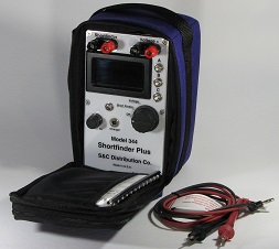 |
The Model 344 Short Finder has capabilities well beyond finding shorts. Among those other applications are:
- Track insulation tester, including insulated joints
- Locating line and cable shorts
- Identifying high-resistance Bonds & Track Connections
- Noisy air gap arrestors, etc.
Also it can be used as a track quality meter for gauging suitability of track conditions to support signal circuits. Many probe accessories are available to improve connection to the rail. Calibrated Test Loads are also available that permit use of the Short Finder to confirm resistance values of signal testing shunts.
The Model 344 Short Finder incorporates corrections to frequently raised criticisms of the older Model 324 Short Finder. The 344 Short Finder will not shunt audio frequency track circuits, motion detectors and constant warning devices. Further, the tuning in the 344 Short Finder blocks spurious AC voltages that previously distorted short finder readings. A new capability of the 344 Short Finder is the addition of a spectrum analyzer. This function allows you to �see� all other voltages appearing on the track whether AC or DC. In the case of AC signals, you can determine both voltage and frequency.
An internal, rechargeable 12VDC, 1.2AH, gel cell battery provides operating current for the 344 Short Finder. Test capabilities are provided by two AC frequencies(switch selectable) 3KHz & 24KHZ. Unit comes complete with probe-type leads, zippered, padded case, and charger/wall box |
| ORDERING REFERENCES |
| Description |
Part Number |
| Model 344 Short Finder, w/Case, Probes Leads & Rechargeable Battery (12V) |
344-1 |
| Replacement, Standard Leads |
324-16 |
|
 File Probes/Leads Set delivers extended reach and mechanical advantage when taking Short Finder readings. Take accurate Short Finder readings, easily through rust, grease and other rail contaminants. Each file/handle combination measures 12" long. Current version offers screw-on leads that are each four feet long and are made of low-temperature lead wire.
| ORDERING REFERENCE |
324-25 |
|
 Quick-Read Probe Tips make using the Short Finder easier in rusty, greasy or contaminated rail environments. Instead of carrying a file, the hacksaw blade Probes scrape through the interfering material covering the rail, switch rods and gage plates, resulting in stable and reliable Short Finder readings. Screw onto threaded shoulders on the original leads furnished with the Short Finder.
| ORDERING REFERENCE |
324-18 |
|
 Dual-Blade Probes/Leads Set provides a mid-range alternative to our Quick-Read Probe Tips and the File Probes. The dual-blade configuration stiffens the assembly and the four inch handle allows some additional reach and mechanical advantage without adding significantly to the weight. A unique lead set screws into the handles of the Dual-Blade Probes. Take accurate Short Finder readings, easily through rust, grease and other rail contaminants. Leads are each four feet long, are made of low-temperature lead wire and are the same as those furnished with later-version File Probes. Set comes with Dual-Blade Probes and Screw-On Leads. Leads are replaceable.
| ORDERING REFERENCE |
324-28A |
|
 Rugged, Meter Lead Rail Connector is based on our railroad-grade Head of Rail Clamp. Furnished with a specialized connector that accommodates screw-in leads. Establish zero ohm connection to the rail that will permit you to use your Short Finder to check for intermittent shorts in insulated joints, etc. Leads that come with the Set can be plugged into any meter that accommodates standard banana plugs. Use the Meter Lead Rail Connectors to assist you in conducting FRA-required Shunt Fouling Test, etc. Set of Clamps come with leads in zippered, padded case.
| ORDERING REFERENCE |
324-31 |
|
 Permit use of Short Finder to check testing shunts for correct resistance. Calibrate the Short Finder on the 3.0KHz frequency and read between the "HW" terminals and the "0.06 Ohms" terminals. These readings are the values you should see when you check your testing shunt. If you do not see these values, your shunt should be repaired or replaced. Test Load can also be furnished for use with shunts with the following resistances: 0.10, 0.15, 0.25 and 2.0 ohms.
| ORDERING REFERENCES |
| Description |
Part Number |
| Any resistance except 2.0 ohms |
324-1(_ _)indicate numbers of the resistance value without using decimal point. |
| Resistance of 2.0 ohm |
324-202 |
|
 For the older Model 324 Short Finder
This Adapter has been developed to convert AC voltages to DC, so that AC voltages can be read by the DC voltmeter built into the 324 Short Finder. Because there is a significant loss across the Adapter, the resultant readings cannot be considered suitable for the purpose of obtaining data. However, they are entirely usable as indicators of the presence of distorting or damaging AC voltages, or for determining whether your track light is on due to an open or a short where conventional AC track circuits are used. This device is not necessary when using the Model 344 Short Finder
| ORDERING REFERENCES |
324-17 |
|
 324-27 Track Probes/Leads Set delivers extended reach and mechanical advantage when taking Short Finder readings. Take accurate Short Finder readings through rust, grease and other rail contaminants. Probes virtually, eliminate the possibility of damage to the rail when taking readings.
Each Probe/handle combination measures 12" long. Probes are hard tool chromed to resist rust and corrosion and Probe tips are hardened to extend service life. Handles have threaded holes that accommodate screw-on-leads. Leads are each four feet long and are made of low-temperature lead wire.
Set comes with Track Probes, Leads, tool pouch and Allen wrench. All pieces are replaceable.
| ORDERING REFERENCES |
324-27 |
|
Narrow Band Shunt Tester

The widespread use of motion sensing and constant warning time track circuits has resulted in the proliferation of wide and narrow band shunts and IJ couplers. Many times the circuits are overlapped, resulting in ever-increasing problems of tuning and frequency conflict. The troubleshooter needs to know the complete range of characteristics of the shunts couplers with which he is dealing, when attempting to identify the source of the circuit malfunctions. This device permits the frequencies, tuning characteristics, Shunts, Couplers, and Transmitters attenuation, thru-put capacities and transmitter output frequencies of each device in the approach �network� empowering him to relatively quickly determine the source of the problem.
- Identify center frequencies of shunts, couplers and related transmitters
- Determine termination and signal thru-put capacities
- With data from tester, rule out shunts as sources of tail ring
- Adjust tunable couplers and shunts prior to installation
- Test for DC leakage
- Frequency range: 10HZ to 5120HZ
- For field or shop use
- Operated on rechargeable, 12VDC, 1.2AH lead acid battery
Application
This highly portable device permits the maintainer to bridge or terminate signals into the shunts or couplers under test. It can be moved to the area of the track where the shunts or couplers are in service, maximizing effectiveness and minimizing time required to perform the tests.
�Sweep� Function automatically check full range for tuning points. Graphic display pictorially shows frequency curves and tuning points.
Separate inputs for Tuning, Leakage and Frequency Meter Tests reduce potential for resistance in switch contacts to adversely affect test results.
| ORDERING REFERENCES |
| Description |
Part Number |
| 322 Tester with 12V rechargeable battery, AC to DC Charger, Leads Carrying Case |
322-2 |
| ACCESSORIES FURNISHED |
| In-Vehicle Charging Adapter |
324-12 |
| Charger/Wall Box, 120VAC to 12VDC, 500mA |
324-11 |
| Lead Set, 4ft. HD Clips |
322-15 |
|
Model 201A Program Transfer Device
 Many S&C products employ programmable chips in their design. A method has been developed that can be used to reprogram a piece of S&C equipment without sending every device to the factory, and will not require specialized software to be installed on the computers of the users of S&C equipment. This method is our Model 201 Program Transfer Device (PTD). The design of the 201 PTD is based on a commercially available product. It will work with every piece of equipment manufactured by S&C Distribution Company that carries a chip that can be reprogrammed.
While our program-operated products do not carry the same sensitivity signal control devices and systems do, we appreciate and support the procedures railroads have developed to insure device program currency. We see the PTD being used following consultation with individual customers. They will distributed in accordance with conclusions reached with the customer. Note: due to the nature of the purchased product, it is not possible for one PTD to program another PTD.
S&C products have achieved widespread acceptance, and the condition exists that a number of different programmed devices are in service on individual railroads. A concept worth considering is that a set of PTD's be maintained for each type of product that may require programming. This practice would reduce mix-ups, and maintain a local-to-the railroad source of the current program for each type of product.
The 201A Program Transfer Device comes complete with all cables necessary for use and a 120VAC to 5VDC Power Supply, in a zippered, padded case. For traceability and determination of ownership, each PTD is identified by its own Serial Number.
- S&C will load a new program into a 201A Program Transfer Device (new or the customer�s, returned to have a new program loaded into it) The PTD is clearly labeled with the Name and Version Number of the program installed.
- We send the programmed Device to the customer.
- The customer:
- Connects the 201 Transfer Device to a power source (5VDC; his computer via USB, or our Power Supply, all necessary equipment provided with the 201A)
- Power-up the S&C product that requires reprogramming.
- Couple the 201A PTD to the input RJ-11 Jack on the main PC board in the S&C product.
- Press the button on the Transfer Device. The S&C product is reprogrammed. CAUTION!
This step requires attention to detail.
There is nothing to prevent a new program from being installed in the wrong product.
- In situations where many units require reprogramming, each regional headquarters might have a number of Transfer Devices to distribute as require
| ORDERING REFERENCES |
| REF |
Product Description |
Part Number |
| A |
Program Transfer Device, Generic, Complete |
201A |
| B |
Above, but w/cur. prog. for 322 Shunt Coupler Tester |
201A-322 |
| C |
Above, but w/cur. prog. for 331-1 DC/AC Relay Slide |
201A-3311 |
| D |
Above, but w/cur. prog. for 331-5 Record Relay Slide |
201A-3315 |
| E |
Above, but w/cur. prog. for 344 Short Finder |
201A-344 |
| F |
Above, but w/cur. prog. for 355 Signalman's Meter |
201A-355 |
| G |
Above, but w/cur. prog. for 401 Impedance Bond Ckr |
201A-401 |
| H |
Above, but w/cur. prog. for 410 Signal Test Timer |
201A-410 |
| J |
Above, but w/cur. prog. for 577 Cab Signal Code Tstr |
201A-577 |
| K |
Above, but w/cur. prog. for 1010 Portable Data Record |
201A-1010 |
| R1 |
Replacement Program Transfer Device, only |
201A-1 |
| R2 |
Replacement RJ-11 Interface Cord |
201-1-1IC |
| R3 |
Replacement 5VDC Power Supply w/USB cord |
201A-PS |
| R4 |
Replacement Zippered, Padded Case |
506-802-12 |
|
Model 500 Jumper Keeper Alarm System

|
The Model 500 Jumper Keeper (US Patent No. 5,917,419) will help a conscientious signalman limit the risk of left-jumpers. Jumper Keeper is inserted into the standard routine of jumper use, requiring no extra effort on the part of the maintainer to achieve the improvements in safety. Responsibility for jumpers is kept where it belongs; with the individual using them. Dash and Rack Unit Set accommodates 6 jumpers. Visual and audible alarms respond when vehicle ignition is on and a jumper is missing. 10 minute time-out is push-button activated and is repeatable. Where more than 6 jumpers are required Extension Rack Units can be used to add jumpers in multiples of 6, up to a total of 30 jumpers. Numbered jumpers with company identification are also available.
|

|
| ORDERING REFERENCES |
| Description |
Part Number |
| Jumper Keeper System |
500A |
| Set of Numbered Jumpers |
500-8 |
| Extension Rack Set |
500A-3 |
|
|
1010 Signalman's Portable Data Recorder
 S&C Distribution Company is pleased to offer a data recorder that addresses the needs of railroad signalmen; particularly for handling clear-on-arrival problems. Our 1010 Portable Data Recorder (PDR) provides the means to monitor up to sixteen contact closures and/or floating outputs such as those provided by GCP�s � or VHLC�s �, and two analog inputs for tracking voltages, and time/date stamp their activity. The PDR is in a package that is designed to be moved from location to location. The use of an SD Card to store the comma delimited data will allow long time intervals to be recorded and then be quickly moved to a computer to assess the data.
Memory capacity is limited only by the size of the SD Card. An 8GB card is furnished, which will provide enough memory to record one incident every ten seconds for 10,767 days, or 29-1/2 years. A real-time clock/calendar date and time stamps each event. To insure complete isolation of the equipment under measurement, the inputs employ opto-coupler interfaces. All eighteen input ports are provided with isolated commons.
Properly time-stamped data collection can begin within one minute of hook-up. Fast-Track set-up utilitzes pushbuttons on the PDR and/or a keyboard or barcode scanner, eliminating the need for a computer for the set-up process.
The PDR can be powered by any or all of three alternatives: local battery (10-16VDC), 120VAC (PN: 324-11 Power Supply provided), and an optional, rechargeable Battery Pack (330-1010A, 12-14VDC). When idling, current usage is approximately 125mA.
S&C Distribution Company is staffed with people who have long experience with railroad signal requirements. As a result, this product contains many railroad-oriented, nice-to-have capabilities not found in generic data recorders.
- USB Port For Keyboard or Scanner Input
- Non-Polar Opto-Coupler Isolated Inputs
- Display Offers Unique Indications: �X� (Up, Active) and �_� (Down, In-Active)
- Digital Inputs Respond to Changes of 0.05 Seconds Duration. Records 1 event per second. If more than one event occurs within the one second, screen displays an �M�, for �multiple�.
- Live Status of All Inputs Visible On the Display
- Unit Will Play Back Stored Data For Viewing On the Display
- Two Analog Inputs Can Record AC (0-150V) and DC (0-75V) at the same time
- Both Analog Inputs Can Be Programmed to Record Voltages Monitored On A Time Interval Basis. Readout simulates a pen recorder, to detect voltage fluctuations
- *Terminals Will Accommodate #20 to #10 AWG Wire
| ORDERING REFERENCES |
| Ref |
Description |
Part Number |
| 1 |
Model 1010 PDR, SD Card, SD Aadapter, 120VAC Power Supply, HD Carry Bag |
1010-2 |
| 2 |
Optional 12VDC, 7AH Batt Pack w/Charger and Connector |
330-1010A |
| 3 |
Optional Barcode Label Scanner, Low Temp |
331-5-17 |
| 4 |
Optional ASCII Keyboard, Portable, w/Case |
331-5-19 |
| 5 |
Barcode Label Printer |
331-5-37 |
| 6 |
USB to SD Card Adapter, replacement |
1010-18 |
| 7 |
SD Card, 8GB, replacement |
1010-15 |
| 8 |
120 VAC to 12VDC Power Supply, replm't |
324-11 |
| 9 |
HD Carry Bag, replacement |
322/331BZB |
|
DAT SERIES TAG-OUT
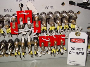 |
Long-honored industrial tag-out safety procedures can now be accomplished with railroad signal systems. Improve the safety of signal system maintenance procedures with these blocks. Designed by knowledgeable signalmen with an understanding of both the industrial procedures, and railroad signal circuits and equipment. Blocks can address all railroad signal system devices that may require tag-out security. Available are single Blocks for various types of test nut switches and RSA terminals, networks of such Blocks for the times where more than one circuit should be interrupted and large paddle Blocks for crossing gate mechanism and switch machine contacts. Individual blocks and networks are punched and can be equipped with DO NOT OPERATE tags for added safety. Kit is available with multiple pieces of common blocks or kits can be configured by the purchaser. All blocks are manufactured from durable, highlight-red, non-conductive, ABS textured plastic. The textured surface helps to retain the Blocks in finger-type contacts.
|
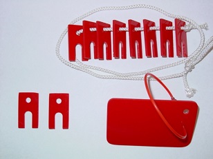 |
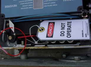 |
| ORDERING REFERENCES |
| Description |
Part Number |
| Single Block for test nuts, etc |
DAT-01 |
| Paddle Block for finger contacts |
DAT-02 |
| String of 8 Single Blocks |
DAT-08 |
| Kit Including 2 each DAT-02 and 2 each DAT-08 |
DAT-03 |
| Red carry bag for Kits |
DAT-98 |
| DO NOT OPERATE tag |
DAT-99 |
|
|
215-15 Dual-Purpose Walking Wheel
 Field-tested by knowledgeable railroad signal personnel, our unique design provides a stay-on the-rail Walking Wheel that is self-guiding and surprisingly easy to propel down the track. During the final field trials, the evaluator was pushing the Wheel down the track with one finger. Adjustable for rail sections from 90 to 150 pounds or heavier, the Wheel stays upright on the rail without assistance under all but the windiest conditions. This Dual-Purpose Wheel is quickly convertible into one that will make fast, accurate measurements on the ground. Simply flip the Sled/Support Assembly up, latch it, and away you go. Fifteen inch diameter wheel equates to a four foot circumference, eating up the distance to be measured, and when on the ground the larger diameter allows the Wheel to measure accurately on rough terrain. Brake provided to lock Wheel when moving to second location to prevent measurement errors.
| ORDERING REFERENCES |
| REF |
Product Description |
Part Number |
| 1 |
Walking Wheel & Sled/Support Assy, complete,15 inch, measures in feet |
215-15 |
| 2 |
Above, but measures in meters |
215-15M |
| 3 |
Sled/Support, only with retaining latch and all hardware |
215-150 |
| 4 |
Replmt. Wheel Assembly w/counter, brake and handle |
215-15-400 |
| 5 |
Replmt. Support Piece & mounting hardware, orange p.c. |
215-15-20 |
| 6 |
Replmt. Sled Piece & mounting hardware, black p.c. |
215-15-10 |
|
205215A Isolated Talker
 The S&C Isolated Talker was developed to be a companion piece of equipment to our Slide Fence and High Water Detector equipment. Inclusion of the word "Isolated" indicates that a ground related to control inputs or the internal workings of the Talker will not ground a signal battery which may be used to power the Talker. Use of an isolated DC to DC converter is required to fully isolate any attached radio electrically, due to the antenna ground. The Talker is designed to either automatically announce the detection of some wayside hazard to train operation via radio or respond to external interrogation through the use of a DTMF code generated by a radio with a touch-tone pad. Upon receipt of the interrogation code, the Talker then generates the appropriate voice message indicating lack or presence of a hazard. A group of five pre-recorded messages (in English), appropriate to use with Slide Fences, High Water Detectors, Dragging Equipment Detectors, High-Wide Load Detectors and Hot Box Detectors can be selected by the user on set-up of the Talker, or the messages can be recorded locally with the built-in electret microphone.
| ORDERING REFERENCES |
| REF |
Product Description |
Part Number |
| A |
Isolated Talker, 12VDC, 4 Control Inputs |
205215A |
| B |
Above, but for 24VDC operation |
205217A |
| C |
Adapter Panel for 19 inch rack mounting of Talker, only |
205215-10 |
| D |
Isolated DC to DC Converter, 12VDC, 13.6VDC/15A Out |
215-CON1675 |
| E |
Isolated DC to DC Converter, 24VDC, 13.6VDC/15A Out |
215-CON1675-24 |
| F |
Radio, 30W, 12VDC operation |
205215-112 |
| G |
Radio, Above, but for 24VDC operation |
205215-124 |
| H |
Antenna for above radio to be determined by location |
N/A |
|
216D and 217D Track Diodes
 Waterproof and highly surge resistant, the 216/217 Series Diodes also offer extra-low insertion loss, notably high current capacity and are repairable. Our Diode was the only brand diode that the surge generator of a major railroad could not blow up. Field tests indicate that our Diode can offer a gain in circuit length, shunting improvement and "hold-in" capacity in bad track conditions. Because the high-current diode itself is heat-sinked, current capacity of our Track Diode exceeds practical limits of the transformer end of the circuit. Aging and burnout of the diode has, for all practical purposes, been eliminated. Further, a unique sealing process allows resealable access to all the components should repair become necessary. Track wires are each 4 feet long.
| ORDERING REFERENCES |
| Description |
Part Number |
| Diode In Clear Case less/Mtg Clamps |
216D |
| Diode In Clear Case w/Mtg Clamps |
216DK |
| Diode In Opaque Case w/Mtg Clamps |
217D |
|
Track Circuit Components 215A Track Power Unit and AC Source Unit

|
AC/DC, Style "C" track circuits have long been recognized for their ability to work properly in rusty rail and bad track environments, and for their ease of maintenance. Adding to our unique Model 216/217 Track Diode, S & C Distribution Company is offering a complete, building-block type, AC/DC track circuit system, including the AC Signal Source and Track Power Units that feed the Track Diode(s). Expanding on the attractive features of AC/DC type circuits in general, use of the AC Source/Track Power Unit concept, which operates on 8-15 VDC, provides a track circuit system that will continue to operate after commercial power has failed, as long as the standby battery has the capacity to power it.
The building-block Model 215A AC/DC Track Circuit System consists of the AC Signal Source Unit (PN: 215B-2), Track Power Unit (PN: 215A-1), and Track Diode (PN: 217D - see above). These building-blocks can be combined to create a wide variety of track circuit configurations. The 215A System offers the advantage of operating on DC power while creating a square wave AC signal to feed the track diode.
Our use of a square-wave AC signal creates optimum shunting characteristics. Because of the very high voltage spikes that are generated by the square-wave signal, shunting characteristics of such signals are superior to DC and even AC sine-wave type signals.
Up to six Track Power Units (TPU's) can be fed by one AC Source Unit (ACSU), allowing a common phase and frequency to be maintained throughout the track circuit group. Using this capability, short approach warning is guarded against by alternating phase alignment on the rail in each circuit.
Single 215A Track Circuits are ideally suited to OS and Fouling Circuit applications. See following information on the 215 AC/DC Single Track Circuit Panel. Additional information is available in sales and application literature.
|

|
| ORDERING REFERENCES |
| Description |
Part Number |
| 215A Track Power Unit |
215A-1 |
| 215A AC Source Unit |
215B-2 |
|
40 Volt Auxiliary Surge Network
 The 40 Volt Auxiliary Surge Network protects our Track and Slide Fence/High Water Detector Power and AC Source Units from surges that get through primary track, line and power-side arrestors. It should not be used as a standalone device.
By holding all five inputs and outputs to a common value not to exceed 200V, it prevents damage caused by fast moving initial spikes and metallic surges resulting from unbalanced circuits. The protective theory employed has been well-proven in the service performance of our Track Diode. Circuits operating through the device should not exceed 38VDC, 38VAC, peak to peak.
The Surge Network mounts directly to either our 215A-1 Track Power Unit or our 215A-10 Slide Fence and High Water Detector Power Unit in lieu of field wiring. Field wiring then connects to the Network. Additional information is available in sales and application literature.
| ORDERING REFERENCES |
215A-18 |
215 AC/DC Single Track Circuit Panel
 S&C Distribution Company is pleased to make available a prewired panel, suitable for backboard or 19" rack mounting, that includes all track circuit specific components for one circuit, except the safety relay. Can be ordered with or without the 40 Volt Auxiliary Surge Network. This handy package makes the job of circuit conversion or new circuit installation a very easy process. When ordering, specify track and limit resistor values.
| ORDERING REFERENCES |
| Description |
Part Number |
| Circuit Panel w/o Aux Surge Network |
215-1020 |
| Circuit Panel w/Aux Surge Network |
215-1021 |
|
Model 200 Slide Fence Pull-Aparts

 A modern solution to an old problem. For use with hog-wire type slide fences. Rugged, UV inhibited plastic housing and lid, with interlocking weather seal. Pull-apart pins are conductive stainless steel. Double pin union requires 40 foot pounds pull to disengage. Comes complete with fence-attaching eye and water-tight couplings for wiring. Slack-adjusting turnbuckle available as an accessory.

| ORDERING REFERENCES |
| Description |
Part Number |
| Double-Pin Pull-Apart |
200-2 |
| Turnbuckle, Slack Adjust |
200-2-3 |
|
205 Series High Water Detectors
 S & C Distribution Company provides a unique series of circuiting solutions to another old problem. Three different High Water Detector options offer two DC versions, one requiring 8 wires from the control case and one requiring four wires; and one AC/DC version requiring two wires. In addition to the simplicity of a two wire circuit, the AC/DC version offers improved sensitivity to less conductive water, without responding to normal nighttime condensation, and the ability to connect Detectors in series to allow one power source to activate a network of Detectors covering as much as 54 linear miles.
The major advances in High Water Detector design actually start with the Detector itself. Maintenance considerations, such as ease of access (lid lifts off, bringing with it all internal components - see above drawings) and ease of testing (Detector is designed to stand off from its mounting post allowing testing with a five gallon bucket half-filled with water) make the Model 205 High Water Detector a very practical device.
Water enters the tube, and drains from it through screened ports drilled in the bottom. Similar screened ports at the top of the Detector insure against air pressure resisting the rise of the water. Water contacting the electrodes shorts the circuit, causing the HWPR relay to de-energize.
Application literature includes circuiting recommendations that incorporate a push-button reset to guard against wave action causing the high water indication to cycle on and off, and forcing the presence of someone capable of evaluating the condition that resulted in detection. An alternate circuit provides for protection against electrolysis resulting from the Detector(s) remaining under water for an extended period of time.
| ORDERING REFERENCES |
| Description |
Part Number |
| High Water Detector, 8 wire, DC |
205-1 |
| High Water Detector, 4 wire, DC |
205-2 |
| High Water Detector, 2 wire, AC/DC |
205-3 |
|
215A Slide Fence & High Water Detector Circuits

|
Our highly successful AC/DC, Style "C" building block track circuit equipment has been modified to address the unique needs of slide fence and high water detector applications. Using this equipment offers several advantages:
- High voltage (14 and 28 VAC) output for working through long, possibly high-resistance circuits.
- Circuit distances of up to 54 miles are possible
- Configurable so that a short anywhere in circuit will cause a detection, rather than a false-clear failure.
- Low current drain allows use of Model 215 equipment at remote locations where solar power is the only option
- If powered by commercial power, following power failure, the 215A-10 Power Unit and the 215B-2 AC Source Unit will continue to operate as long as the associated standby battery has the capacity to power them.
- Diode is housed in a rugged, stand-alone, waterproof housing and has superior, built-in lightning protection.
Full application details are available on both the Slide Fence and High Water Detector Circuits. See also above information on the 40 Volt Auxiliary Surge Network accessory available for use with the 215A-10 Power Unit.
|
|
|
| ORDERING REFERENCES |
| Description |
Part Number |
| 215A SF & HWD Power Unit |
215A-10 |
| 215A AC Source Unit |
215B-2 |
|
215 AC/DC Single Slide Fence and High Water Detector Circuit Panel
 We are pleased to make available a prewired panel, suitable for backboard or 19 in. rack mounting, that includes all the circuit specific components for one circuit, except the safety relay. Can be ordered with or without the 40 Volt Auxiliary Surge Network. This handy package makes the job of circuit conversion or new circuit installation a very short process.
| ORDERING REFERENCES |
| Description |
Part Number |
| Circuit Panel w/o Aux Surge Network |
215-2020 |
| Circuit Panel w/Aux Surge Network |
215-2021 |
|
POK Strobe Light
 S&C Distribution Company is pleased to offer a unique solution to the problem of power off indication. Our 120 POK Strobe Light is turned on when commercial power fails, rather than being turned off. It is much easier to see an active strobe light, particularly when your primary concern is the possible presence of fuel trucks, etc., at the crossing, rather than looking for something that is off. Over the years, widespread use of this light has established a nearly 100% success rate at having power-off conditions reported from the field, usually by train crews. Further, because it is only on when an alarm condition exits, vandalism rates are a small fraction of those recorded for conventional power-off indicators.
While POK service at highway crossing warning locations is a primary application, other locations where our Strobe Light is in service include hot box detector and train control signal sites. The product we offer is unusually well suited to the purpose. Two operating voltages are offered; 6 to 10VDC and 6 to 24VDC. Two activation methods are available; industrial relay and 120-30 Voltage Sensor (see following). Contact us for more application information.
| ORDERING REFERENCES |
| Description |
Part Number |
| POK Strobe Light, 6-10VDC |
120-10 |
| POK Strobe Light, 6-24VDC |
120-24 |
| PO Relay, 120VAC |
120-16 |
| PO Relay, 240VAC |
120-17 |
|
Model 120 DC Voltage Sensor
 Easy-to-apply activator for various PO indicators. Specifically designed as activator for the S&C Mode 120 POK Strobe Light, however the unit can drive assorted DC relays (200mA relay drive output) or provide inputs to recorders or other reporting devices. This unit is field-configurable to allow for an output either when sensed voltage is present, or when it is not present. Green LED indicates Input voltage presence and Yellow LED indicates Output presence. Sensor features very low current usage during monitoring operations. Unit is designed to respond to storage battery output thus, checking commercial power, battery charger and the operating battery itself. Any failure in the chain will be detected and alarmed. Monitors DC voltages from 6 to 30 VDC. Range selection is made on installation. Fine tuning of the detection point is accomplished with an adjustment pot. Set this unit to detect when the float charge to the battery drops. Additional application details are available.
| ORDERING REFERENCE |
120-30DC |
|
Back to the top
|


 Because there are a variety of rectifiers used with PO relays, there is a need to simulate their different characteristics. Testing a PO relay out of the rack with a rectifier of a configuration different rom that used to determine pick and drop characteristics, originally, can produce test results that are considerably different from the values on the relay label. This Adapter allows you to toggle between simulators of the two basic types of rectifiers (Silicone and Selenium) because you will not know what type of rectifier was used to determine the pick and drop values. You have a 50-50 chance of guessing wrong. One way or the other you have a way of quickly getting valid test results. Works with the 331 Slide.
 "Railroad rugged" smallest comprehensive signal relay tester. Volt and ohmmeter provide simultaneous readouts. Include polarity reversing switch and LED "power-on" indicator. Two models: 2.0A max. output, 3-turn and 10-turn pots. Come in padded case with leads (relay test and local battery). Optional equipment includes: battery packs, AC to DC power supply, in-vehicle chargers, adapter for use with plug-in relays out of the rack, long-reach probes for use with plug-in relays in the rack, searchlight signal testing adapters and shoulder harnesses.
 120VAC to 16VAC low voltage output for testing power off relays. Can be used with 331 DC/AC Relay Slides. Unit is fuse protected. AC power supply for testing PO relays.
 Makes out-of-the-rack testing of plug-in track and line relays faster and easier. With the 332 AC Relay Slide, permits the testing of out of the rack, of plug-in PO relays with silicon rectifiers. There is no need to rig up a rectifier.
 To operate correctly, the Model 332 AC Relay Slide requires an AC voltage that provides a true sine wave, 50-60Hz. Most, if not all, vehicle-mounted inverters provide a square wave output, which will cause damage to our AC Slide that will require shop repair. Many older signal locations are not equipped with standard outlets, although the 120 or 240 VAC power is in the case. Our 332-20 Test Equipment Power Adapter allows the user, using good safety practice including opening the incoming 120/240 circuit before connecting the Adapter, to power any S&C Slide (AC or DC) or Megohmmeter from the existing commercial power.
 Long-Reach Probes and Leads offered by S&C Distribution Company, permit the user to slide GRS/Alstom and Safetran Plug-In Relays from the front, as long as both positive and negative terminals are accessible. Can be used with any meter that is equipped with standard banana jacks, five-way terminals, etc. Probes are 8.5 in. long and each is equipped with a 3.0A, fast-acting fuse. Leads are 8.0 ft. long with silicon insulation featuring an operating temperature range of -58 deg. F to +356 deg F.
 Our 330 Series DC Relay Slides have long been used to test Searchlight Signal Mechanisms for proper motion and proper pick and drop values. Our Testing Adapter Kits are comprised of three main components, as the photo indicates (Shown is the 330-25 Adapter Kit for H2 Signal Mechanisms). Those components are Slide Adapter, Signal Adapter and an Interconnect Cable. Can be used on plug-in or hardwired searchlight signals.
 Lead sets in popular configurations. Come with either alligator or battery clip connectors, right angle plugs. Wire is No. 18 Test Lead wire with silicone insulation for flexibility in low temperatures. For reliability and durability, insulation is mechanically restrained and the wire itself is soldered to the clip connection point. Leads are sold in sets of two (one red, one black).
 In response to numerous request from signalman, we have developed a multi-meter for common signal maintenance needs, based on currently available technology. While the unit is digital, it also offers an analog display (bar graph) for each scale, for those who prefer such an indication. The use of modern technology allows several additional features that relate to today�s signal maintenance requirements. With nearly 250 years of collective railroad signal experience to guide us, we have also been able to address some shortcomings of the meters traditionally used for this purpose.


